Design of column formwork
|
|
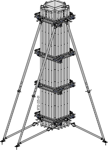
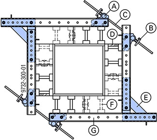
NOTICE ▪ To achieve exact plumbing & aligning of the column formwork, the best arrangement of the panel struts is as illustrated here. ▪ Always attach panel struts to free-standing formwork halves to prevent them from falling over. |

The Corner connecting plate 90/50 connects the walings rigidly and precisely across the corner.
Together with tie rods, the Universal angle tie bracket enables the walings to be diagonally tension-braced.
|
|
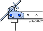
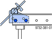
CAUTION Risk of tie overload if not correctly positioned! ➤ Make sure that the Universal angle tie bracket is bolted into the right holes for the Multi-purpose waling WS10 Top50 or WU12 Top50, depending on which type of waling is being used! |

|
Pinning holes for Multi-purpose waling WS10 Top50 |
Pinning holes for Multi-purpose waling WU12 Top50 |
|---|---|
|
|
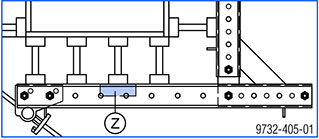
Note:
To prevent deformation of the waling profiles, put a site-provided wooden spacer (Z) between the profiles of each waling and nail it to the Doka beam.
|
A Universal angle tie bracket |
|
B Wing nut 15.0 |
|
C Tie rod 15.0 |
|
D Flange reinforcement |
|
E Corner connecting plate 90/50 |
|
F Doka beam H20 |
|
G Multi-purpose waling |
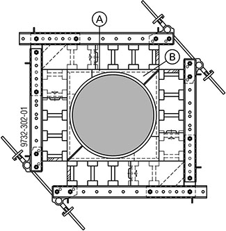
Circular column formwork
|
A Spacer plank |
|
B Profiled timber former |
Rectangular column formwork
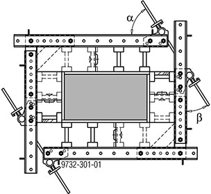
As far as possible, set the angles of the form ties in the same ratio as the length-to-width ratio of the column cross section.
α : β ≈ length : width
.